How To Build A Bedini Motor Series - Final Assembly
This is the finaly steps in the assembly of the Bedini Motor which can desulfate lead acid batteries and restore them to like new (or better) condition.
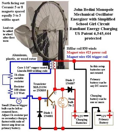
Today I soldered all the electronics components together following the schematic that John Bedini shared with us many years ago. This is the Simplified School Girl circuit. It gots its name because John gave the drawings to a school girl who won a science contest with the little machine she built. This device ran off a 9 volt battery while powering an LED much longer than it should have.
First, set your coil on the table with the bedinnig of the coil on the bottom. This would be the wires that lead to the inside of the coil core.
Now the end of the coil should be on top. Spread out the wires with the thinner wires on the left side and the thicker wires on the right side.
When you refer to the schematic diagram, the coil is drawn just how you have your coil sitting right now.
The bottom of the coil is on the bottom on the drawing.
You must decide if you are going to solder the parts together or use crimp on end connectors. Either way is fine for this project.
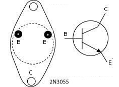
Look at the transistor with the pins facing up. The pins are offset on one side. They are closer to the edge on one side. This helps you identify the transistor pins. Please refer to the diagram below.

2N3055 Transistor Pinout Diagram
NOTE: the case of the transistor is also the collector. Keep this in mind because touching bare wires or components to the case of the transistor can short it out or burn it.
Now, we are going to use the schematic diagram quite heavily so you may want to print this out so you can refer to it often.

Bedini SSG (Simplified School Girl) Motor Diagram
I chose to solder the components together.
Place the coil under your wheel (if mounted vertically) and make sure it is about 1/8 to 1/4 inch away from the magnets. You want to secure the coil so it cannot hit a passing magnet. I propped mine up with pieces of wood. I can later add or remove boards of varying thickness to adjust the coil height.
First I wound the 1N4001 diode onto the two legs of the transistor. Make sure you have it on the right way before you solder or crimp the connections. The silver band on the diode corresponds with the black band on the diagram above and connects to the Emitter of the transistor.
Connect the 1N4007 diode to the Collector of the transistor. Wrap the lead around the open hole in the case of the transistor and solder it in place. Be sure the silver band is away from the transistor, on the opposite leg.
You can also connect the neon light to the transistor Emitter pin and to the Collector. Itis easy to wrap the wire to the diode wires which are left extended out.
Now strip the wires of your coil ends. There will be four wire ends. Use a knife and carefully scrape off all the enamel for about a quarter inch. Make sure you get it off all the way around, exposing bare wire. You want to be able to make a good electrical connection.
Take the bottom power coil wire (the thicker wire) and solder it to the Collector (case) of the transistor.
Take the bottom trigger wire (thinner wire) and solder it to the transistor Emitter pin along with the diode and neon light.
Solder one leg of the grain of wheat light bulb onto the Emitter pin of the transistor. Then connect the other wire to your 100 Ohm resistor.
Now wrap the other wire of the resistor around two pins of the variable resistor (Potentiometer), covering one of the outer pins and the middle pin. Wrap them securely together and solder the wire in place.
Run the final coil trigger wire (bottom thin wire) to the other end of the variable resistor.
And finally you can now connect the battery wires to the circuit. Use at least 12 gauge (or larger) wire for the next steps.
Take a red wire and a black wire and twist one end together. This connection goes to the final coil power wire (top thick wire). Put color coordinated aligator clamps on the other wire ends.
Connect another red wire to the end of the diode coming off the case (Collector) of the transistor and put an aligator clamp on the other end.
And finally connect a black wire to the Emitter of the transistor and put an aligator clamp on the other end.
Go over all your connections and make sure everything is in the right place. Take your time and check things out thoroughly. Make sure your solder or crimp connections are good and solid.
Your circuit is finished and ready to try out for the first time.
Look again at the diagram and carefully connect the batteries as shown.
Connect discharged battery as the charging battery and a fully charged battery as the run battery.
Take your time and connect the charging battery first. Make sure you get the wires correct.
Get a volt meter handy and connect it to the charging battery. Turn on the meter and watch the display as you proceed.
Turn the resistor all the way to one end and give the wheel a spin up. If you hear a squealing noise then you just have to turn the resistor to the other end.
With the wheel spinning, the grain of wheat light bulb should be glowing. If the neon lights up immediately disconnect the power battery and stop the wheel from spinning. The neon is an emergency indicator and tells you that the charging battery is either too low to recognize or that it is not connected at all.
You can adjust the variable resistor until the grain of wheat light bulb is barely glowing. The charging battery should be showing an increasing voltage.
For now we will leave it at that. I will go into more details on fine tuning your Bedini Motor in the next article.
You can watch today's video here:  Building A Bedini Motor The Electronics
While you are over there please subscribe to my YouTube channel and follow our daily videos as we strive to become self sufficient and off the grid on a budget.
Feel free to ask any questions or get help with your project on our
About the Author
| Troy Reid |


