
Beginners Electronics ~ Understanding The Resistor and Potentiometer
Understanding The Resistor and Potentiometer
The humble resistor is one of the most common electronics components in use today. The resistor does just what its name implies - it resists the flow of electricity in a circuit.
A resistor is rated in Ohms. The higher the number in Ohms, the higher the resistance - or the more it resists the flow of electricity in a circuit.
Below is a photo of a resistor. This is a very simple tube shaped device with colored bands around it. There are generally 4 colored bands but sometimes there could be 5 to 6 bands. The most commonly found resistor has only four colored bands so we are going to stick with this type for simplicity. I have rarely ever seen the other two types.
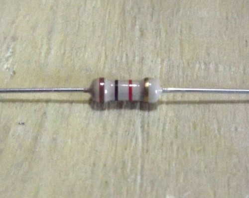
A common resistor
The resistor shown in the image above is one of the most commonly used sizes. The color bands are brown, black and red when looking from left to right. Then there is a gold colored band on the far right side. Lets refer to the resistor color code chart shown below for reference as we talk about resistor color codes and their meanings.
Each color has a value assigned to it. There are ten colors ranging from 0 to 9 in value with black being equal to zero and white representing 9.
The first two color bands are the first two digits in the resistor value. The third color band represents the multiplier.
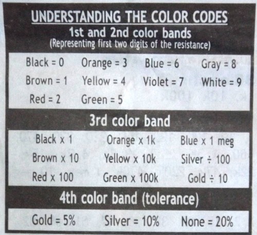
Resistor color code chart
Lets take the example resistor shown in the first image. This resistor has the color bands Brown, Black and Red. So, referring to the chart above, we get the values of 1 and 0 for the first two color bands.
The third band is the multiplier. This color is red. So we have the value of x 100. Lets do the math and see what this resistor's value equals.
Brown = 1
Black = 0
Red = x 100
10 x 100 = 1,000 Ohms
In electronics we abbreviate the numbers to thousands. So 1,000 = 1K ohm resistance. This is a 1 K Ohm resistor.
For more details on reading resistor color charts, please see this article: Resistor Color Code Chart & Resistor Identification
The fourth color band on a common resistor represents the tolerance level, or precision of the resistor. If there is no color band the tolerance is +-20%. This means that the acual value of the resistor can vary as much as plus or minus 20 percent of the rated value. For many circuits this is fine.
But for some precision circuits you may need a more accurate resistor so we have the gold and silver color bands. Silver represents +-10% and gold represents +-5% accuracy.
The resistor schematic is shown in the drawing below. A schematic diagram is what we use to put together circuits on paper. Each electronic component has its own schematic diagram so that we can assemble drawings of circuits for others to follow.
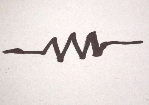
Resistor schematic diagram
There is no wrong direction to insert a resistor in a circuit. There is no positive or negative terminal. You can use any of the two leads that you desire.
A Variable Resistor or Potentiometer
A variable resistor is also often called a Potentiometer or POT for short. This component does exactly what its name implies. You can adjust, or vary, the resistance of the component.
A variable resistor looks something like the one shown in the photo below.
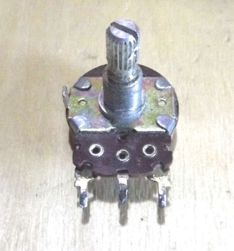
A common variable resistor also known as a Potentiometer
The variable resistor can be adjusted to give a different amount of resistance. By turning the dial in the center, you can increase or lower its resistance throughout its entire range. Lets say, for example, this Potentiometer is valued at 1,000 Ohms, or 1K Ohms resistance.
By turning the dial all the way in one direction, you can turn it down to zero Ohms, or 0 Ohms. By turning the dial all the way in the other direction you can adjust it to its maximum value of 1K Ohms. By turning it to the center you can get about 500 Ohms, which is half of the rated resistance of the variable resistor.
The variable resistor, or Potentiometer, is valuable in many circuits. You may have seen them in use in an older car stereo or television for example. The dial that you use to adjust the volume of your TV or stereo is a variable resistor. The color, saturation and hue adjustments in older tube style televisions are actually variable resistors working behind the scenes. In some refridgerators you may find a variable resistor behind the dial when you set the temperature level to colder or warmer.
Here is a variable resistor (Potentiometer) schematic diagram:
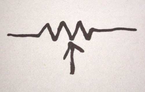
Variable resistor schematic diagram
The drawing above shows a Potentiometer schematic diagram. You can see that it looks just like the diagram of a normal resistor except that it has something added. The arrow which is added to the drawing is called the wiper. This is the adjustable part of the resistor, connected to the dial or knob. When you turn the knob, you are moving the wiper across the resistor, changing its resistance either up or down.
There are no positive or negative terminals on a variable resistor. Sometimes you will use all three terminals or just two. You can connect this device in either direction in a circuit and it will still work the same way.
For some more interesing information about resistors, please see the following two articles and their videos.
How To Measure Resistance With An Analog Multimeter
How to measure resistance with a digital ohm meter
Feel free to ask any questions or get help with your project on our 
About the Author
| Troy Reid |


