DIY Portable Lithium Battery Capacity Testing Station
Budget DIY Lithium Battery Capacity Testing Station
Battery Powered And Portable
I have about 3,000 Lithium Ion batteries that I got dirt cheap from batteryhookup.com which I am charging and testing every day now. I get 10 pounds of batteries for only $8.50 and so far most are turning out very good. Use the code DIYTUBE and save 5% on every purchase.
One problem that I have here is that our grid power is very unreliable in winter months. It has been flickering on and off every couple days when the wind blows or snow falls. Each time the power flickers, it resets my battery capacity testers. It takes 4 to 8 hours to charge a battery and another 4 to 8 hours to run the capacity test and another 4 to 8 hours to charge it back up again. Break the test and I lose an entire day of work.
Our off grid solar power is not much better for this purpose because during long periods of clouds, I shut it all down and give the batteries a rest so I do not over dishcarge them and cause them harm.
So I came up with the idea of building a portable, battery powered Lithium Ion capacity testing station. This can be charged by USB with a solar panel, off grid power or grid power. I plan to use a USB solar panel to recharge the battery as needed for free.

Portable Lithium Battery Capacity Testing Station
I have purchased every part of this project from Amazon and I will share the links below for your convenience. The total cost of the project was not too bad considering that now I have a stable and portable platform.
I got a piece of scrap plywood from the garage and then went to the hardware store to get screws that would fit through the board and into the standoffs that I have. The original ones would have worked fine but I could not get the right sized screws so I used some brass standoffs that I have on hand already.
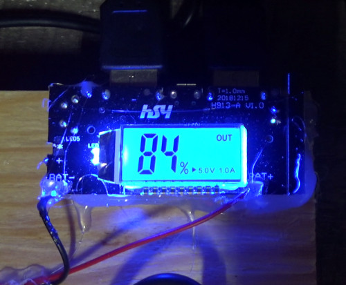
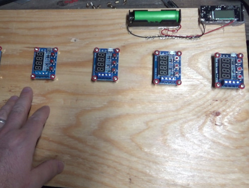
First I screwed down an 18650 battery holder and soldered the terminals to a dual USB output battery charger and power bank circuit. This has a nice digital display which shows battery capacity and output power. It has a 1.0 amp and a 2.1 amp USB output as well as a micro USB charging input to keep the battery topped off when not in use. Then I used my hot glue gun to fasten the circuit board to the wood base. I could not find screws that would fit the mounting holes in the board so I just glued it down. If I am careful this will hold forever for me just fine. Next time I may use some wood dowels and some tiny screws to hold it up off the base board. If you have access to a 3D printer you can make a very nice holder for the circuit board.

Mounting the power supply parts

Closeup of dual USB power bank circuit
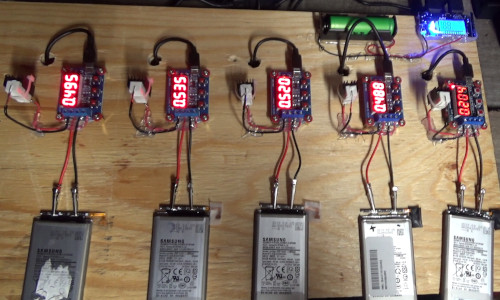
I mounted the battery capacity testing boards on the wood base with enough space in between to allow me to insert or remove batteries on the fly without shorting anything out. To do this I simply placed a circuit on the base board and traced the mounting holes with an ink pen. Then I drilled them out. I made space for 7 circuits. I only have enough screws for 5 circuits at this time so I will get the other two mounted later when I do some modifications to this board. More about this later at the end of this article. Because the screws I got were a bit too long I used PC motherboard washers to space out things to fit better. See the video (link below) for details.

Mounting the battery capacity testers
I used solid core wire and bent it to make a base and extension for the power resistors. This allows me to put them off to the side to keep heat away from the circuit and leave room to insert or remove leads from the screw terminals of the capacity tester boards. I soldered the resistors in place and then fastened transistor heat sinks with thermal compound onto them with zip ties. I have tried this before and it works very well. The heat sinks will move heat away from the resistors and extend their life considerably. I may add some small fans later for even longer life.
I drilled holes in the base board to pass USB charging cables through to power each circuit board. This keeps the wires on the back side of the board and keeps things neat and organized.
And finally I cut some testing leads with alligator clips to make connectors for my batteries. The leads came in a pack of 50 for under $10. This is cheap and saves me time and effort compared to cutting and soldering wires onto alligator clamps myself.
I used hot glue to hold the resistors neatly in place and also to keep stress off the wires on the screw terminals of each battery capacity tester. This will prevent them from breaking off or falling out during prolonged use. I will be using these ciruits heavily, all day, every day on my batteries.
When I turn on the power, all the circuits come on and work just fine. Now I will never lose power halfway through a battery capacity test and have to start over again. And I can move the entire board around as needed to clear up my work bench for other projects. I carried the entire circuit over to show my wife as it was running a capacity test to demonstrate its convenient mobility.
Parts List For The Battery Capacity Testing Station
Lithium Ion Battery Capacity Tester/Meter
50 Back Alligator Test Lead Set
Dual USB 18650 Charger Power Bank
Plans For Future Upgrades
First, of course, I plan to mount the last two circuits to the board so I have a total of 7 lithium battery capacity testers.
In the past I have only run one or two of these at a time and the power consumption was very low. I am noticing that with many circuits, the power battery drains too fast. I would advise using parallel batteries for longer run time in between charges. My goal is to be able to run these circuits all day long and then recharge them later.
As mentioned above in the article, I plan to get some small fans to help remove the heat from the power resistors. This will greatly extend their life time. I will look for some low power fans for this and I will likely use a separate battery to run them.
In the video I mentioned that I will make my own USB power strip instead of using a mess of USB splitter cables. I will have a single input that plugs into the power bank with 7 USB outputs to power the circuits. This will be neater and take up less space under the board.
I will probably put some feet under the board to keep pressure and stress off the wires underneath.
I will do all these upgrades on video and in an article so stay tuned.
About the Author
| Troy Reid |


