
Bedini Style Motor Using Car Relay - Imhotep design
People have been asking me for a long time to show them how to make a Bedini motor. While I am gathering up the materials to make a full scale motor I will show you how to make a small one using a car relay.
This is a design from a man called Imhotep on the internet. I have used this circuit in the past but lost it during a move long ago. Since then I wanted to make another one and now the time has come. I have my new electronics lab set up and ready for work.
This is a very simple circuit which will demonstrate the use of back EMF to charge a battery. Back EMF is the collapsing field in a coil which is in opposite polarity to the one you put into it. When you pulse electricity into a coil it is turned into magnetism in the coil. When you remove the electricity the magnetic field collapses. Moving magnetic fields produce electricity. So you get an opposite voltage coming out of the coil.
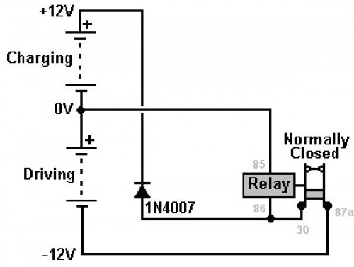
 Bedini type car relay battery charger circuit
In normal circuits this opposite voltage is dumped or grounded to protect the circuitry. In our case we are going to use that energy to charge a battery.
The relay is just like a simple door buzzer in this case. It self oscillates by using the normally closed connection on the relay. When you apply 12 volts DC to the coil, it becomes a magnet which pulls the switch to the open position. This then disconnects power to the coil. Then the switch moves back to the closed position, making contact and allowing energy to flow into the coil again. This repeats very rapidly until you remove power.
With each pulse of energy into the relay coil, you get a pulse of energy out. We dump that into a battery to be charged using a single diode to route the energy. A diode is like a one way valve, only allowing electricity to flow in one direction and blocking it in the other direction.
Here are the parts needed. I have sourced everything for your convenience. You can order the parts easily right on Amazon.
Parts list:
Automotive relay switch: Click here to order
1N4007 diode: Click here to order
Connecting wire (Get one spool red, one black): Click here to order
Crimp on end connectors: Click here to order
Terminal strip (at least 5 positions): Click here to order
2x lead acid batteries: Click here to order
Small wood screws: Click here to order
Small block of wood
Tools needed
Wire stripper/crimper tool: Click here to order
Small screw driver: Click here to order
Digital multimeter: Click here to order
Notes:
If you plan to build the larger Bedini motor along with me later on, some of the materials listed above will also be useful on that project as well. You will be able to use the batteries to experiment with the Bedini motor for one thing. The crimp on end connectors may also be useful as well as the tools listed above. You will also need another 1N4007 diode to make the larger Bedini motor.
On the link given, you may see some automotive relays with wire already included. This will make your project easier to assemble if you choose this model.
Use any block of wood, acrylic or plastic to give you a nice platform to hold your radiant energy device together.
This device is often called a radiant energy device or generator. Some call it a back EMF battery charger. Some will argue that nothing happens in this circuit. Some will argue that all you are doing is a one to one battery charge. But in truth, you cannot charge up one battery while discharging another battery of the same size and type. If you connect two batteries directly then what happens is that the two will level off at the same voltage. The weaker battery will draw from the stronger battery until they both have the same voltage. Then they rest at that point.
In this case you will see that the run battery actually drains down until you disconnect it from the circuit. The charge battery will continue to take a charge until you shut down the circuit. So already you should see something unusual here.
This is a very small scale device so do not expect to restore 100 AH lead acid batteries. You may, with time, be able to restore some smaller 5 and 7 AH lead acid batteries or some AA and AAA batteries with this device.
Have fun, experiment with it.
But be careful!! Working with batteries can be dangerous. Remove all jewelry and metal before working with batteries. Have a clean work space free of clutter. The project shown here is for demonstration purposes only. I am in no way telling you to make this device. I accept and assume no responsibility for any accidents that may occur if you take on this project. Work smart. Be careful. Have fun.
Ok, lets get started
Use a small piece of wood to hold everything together. First place your terminal strip on the botom of your block of wood and fasten it with two wood screws, one on each end. Next, if your relay has a screw hold, fasten it into place on the top of your block of wood using one screw.
Now comes the wiring. Do not be afraid to jump in and learn by doing.
Here is the circuit that I used:
Here is the relay wiring diagram. Please refer to this diagram as we proceed with the wiring of our circuit.
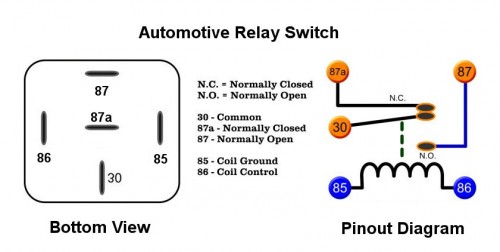
In the image above, you see the physical pins on the left side and the wiring diagram on the right side. You do not have to understand the wiring diagram if you have no electronics experience. You can refer to the physical pins on the left side for now.
First cut a wire to fit from pin 86 of the relay to the center of your terminal strip. Put a crimp on end connector on one end of the wire and strip the other end bare. Slide the crimp on end connector onto pin 86 of the relay and fasten the other end into the terminal strip. I find it helps to split the wire end in half so that it wraps around the screw on the terminal strip better if you have the open top version like I have. Some terminal strips have a hold where you slide the wire inside. In this case you just twist the wire end so that there are no stray wires sticking out.
Next cut two pieces of wire about the same size. These will both tie into the same pin on the terminal strip. One goes to the common pin of the relay (pin 30) and the other goes to the relay pin 85. Slide the end connectors onto the relay and fasten the other ends into the terminal strip as shown in the video.
At the same time you will take your 1N4007 diode and screw it into the terminal strip along with the last two wires. Put the end without the silver band into the terminal strip along with the last two wires. The other end of the diode, the one with the silver band, will go into the next terminal strip on the right side of the last one. Please refer to the video for help here.
Now cut a wire to fit the center pin of your relay, pin 87a. Connect this wire to the far left side of your terminal strip, the last screw on the left.
Now, finally we are ready to connect the battery terminals to the circuit. Measure out about a foot of wire each. You will want two red wires and two black wires. Connect slide on end connectors to one end of each of your four wires. Strip the other ends bare.
Now connect one of the black wires to the far left screw on your terminal strip. This is going to be the negative wire on your run battery. The run battery is the one which will power the circuit.
Now connect a red wire to the center screw on your terminals strip. The one which connects to pin 85 of your relay switch. Run this wire off to the left side with the first black wire.
Now connect a black wire into the same screw and run it off to the right side of your board. This is the negative lead of the battery which is to be charged.
And finally connect a red wire to the far right screw on your terminal strip. This wire connects to the diode end with the silver band. This is the positive wire going to the battery to be charged.
Now we are ready to try out our new Bedini style relay circuit.
First connect the wires to your battery to be charged. Always connect this battery first or you can damage the relay.
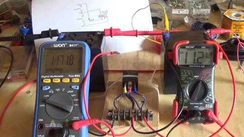
And finally connect the leads to the run battery. The circuit should immediately start to buzz. This is normal and means that your circuit is working well.
Use a volt meter to test your batteries. The one on the left side should be slowly dropping in charge. The battery on the right side should be slowly gaining in charge.
If you are lucky, the battery being charged will be topped off before the run battery is drained. Generally this is not the case though because there are losses in the wires and in the relay coil.
Feel free to experiment with various sized batteries and types. Some people have seen success using this circuit to charge up AA, AAA, and other rechargeable batteries as well as 6 and 12 volt batteries.
Stay tuned for the full scale Bedini motor coming soon....
You can watch today's video here: How To Make Mini Bedini Style Circuit Using Car Relay ~ Imhotep Variant
While you are over there please subscribe to my YouTube channel and follow our daily videos as we strive to become self sufficient and off the grid on a budget.
About the Author
| Troy Reid |


